.webp)
.webp)
.webp)


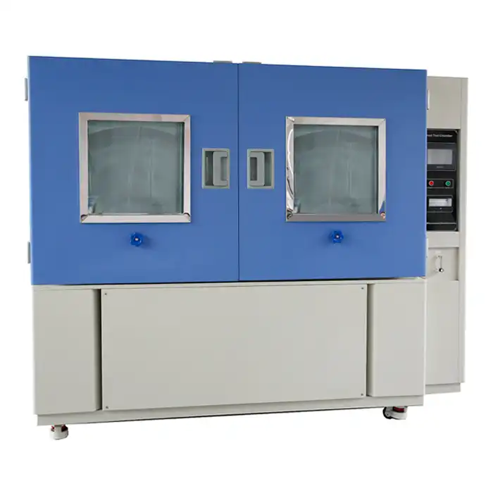
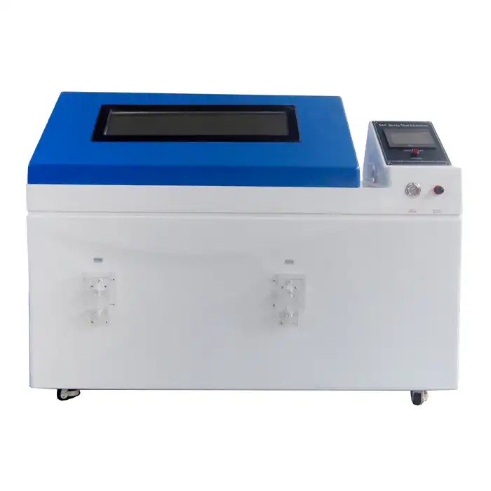
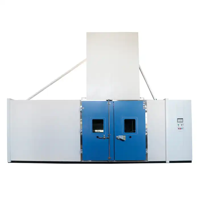
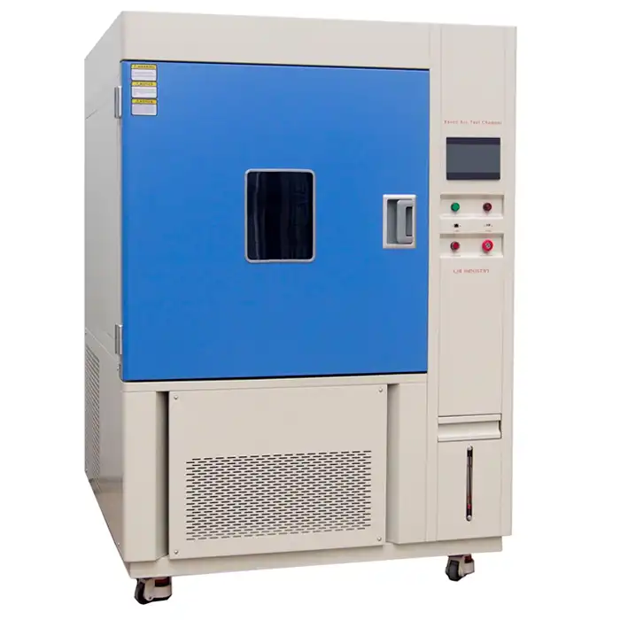
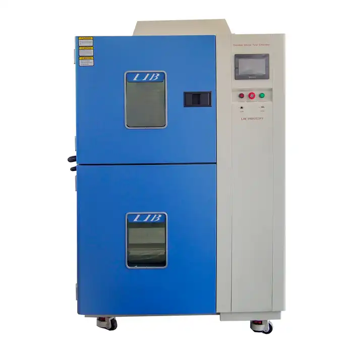
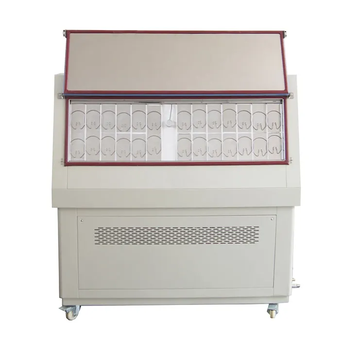
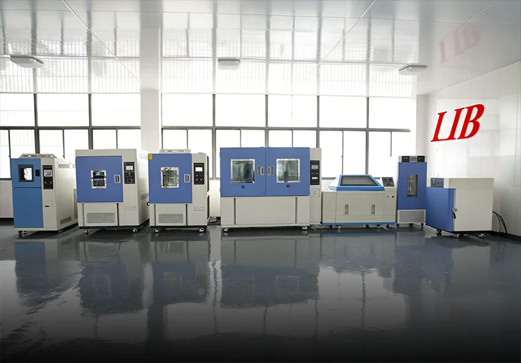
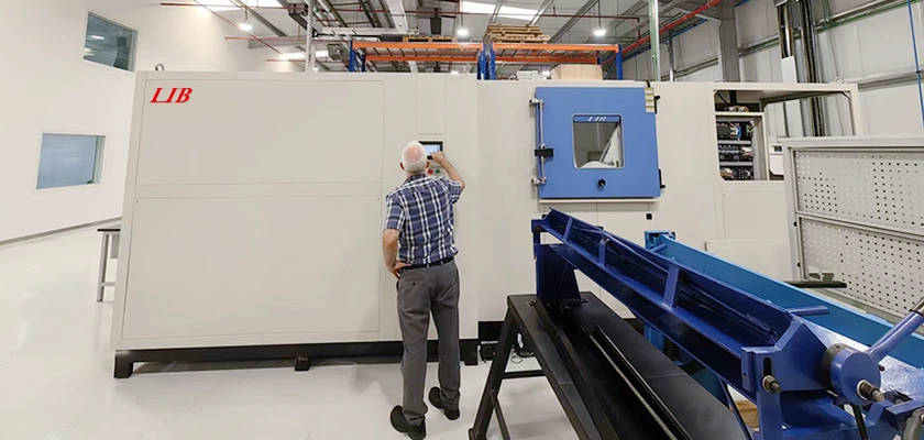
LIB Main Environmental Test Chambers
_1773978265973.jpg)
.jpg)


Chosen by Leading Brands Worldwide
Blog recommendations
Thermal Cycling Equipment in Solar Panel Durability Testing
Solar panels endure relentless temperature swings throughout their 25-to-30-year service life - baking under midday sun, then cooling sharply after sunset. Thermal cycling equipment replicates these punishing fluctuations inside a controlled laboratory environment, subjecting photovoltaic (PV) modules to repeated temperature ramps between extremes such as -40°C and +85°C. This accelerated stress exposes latent weaknesses in solder ribbons, encapsulant layers, glass-cell interfaces, and electrical connections long before panels reach rooftops. By compressing years of field exposure into weeks of laboratory testing, engineers gain the failure-mode data needed to refine materials, optimize manufacturing processes, and validate the long-term power output warranties that underpin investor confidence in solar energy projects worldwide.

A leading electronics testing lab shared their experience with our THR10-500A Thermal cycling equipmentand drying ovens: "Our THR10-500A chamber and drying ovens are working excellently, thank you. We are very happy with them." The stable performance of the chamber during intensive thermal cycling tests enabled the team to conduct extended burn-in procedures and repeated rapid temperature transitions without interruption. This reliability gave them confidence in accurately assessing the thermal resilience and durability of automotive electronics, sensors, and control modules. Beyond electronics, the equipment has proven highly effective in materials testing, plastic component aging, and battery performance evaluations, helping teams efficiently simulate real-world thermal conditions and optimize product longevity.
Why Solar Panels Require Thermal Cycling Testing?

 Decades of Outdoor Exposure and Temperature Extremes
A rooftop or ground-mounted solar array faces unshielded exposure to seasonal extremes - scorching summers, freezing winters, and everything between. Desert installations experience daily temperature differentials exceeding 50°C, while Nordic sites endure prolonged sub-zero conditions. Over a 25-year warranty period, a single panel can accumulate tens of thousands of thermal cycles, each one incrementally stressing internal interfaces and interconnects.
Cumulative Fatigue Mechanisms in PV Modules
Each temperature swing induces micro-scale expansion and contraction across dissimilar materials bonded together inside the module laminate. Fatigue cracks nucleate at stress concentration points - particularly solder joints connecting silicon cells to copper ribbons - and propagate cycle after cycle. Without thermal cycling evaluation, these slow-growing defects escape detection during routine electrical inspection at the factory gate.
Economic Stakes of Premature Panel Degradation
Solar project economics depend on predictable energy yield over decades. A module that degrades faster than warranted erodes investor returns, triggers warranty claims, and damages manufacturer reputation. Rigorous thermal cycling qualification using purpose-built test chambers catches vulnerable designs early, allowing corrections that safeguard both revenue streams and brand equity.
Temperature Stress in Photovoltaic Modules and Materials
CTE Mismatch Across Multi-Layer Module Stacks
Solar modules are laminated sandwiches - tempered glass, ethylene-vinyl acetate (EVA) encapsulant, silicon cells with metallic interconnects, a polymeric backsheet, and an aluminum frame. Each layer possesses a distinct coefficient of thermal expansion (CTE). When temperature changes, these layers stretch or contract at different rates, generating shear and peel stresses at every bonded interface.
Table 1: CTE Values of Common PV Module Materials
|
Material |
Approximate CTE (ppm/°C) |
Role in Module |
|
Tempered glass |
8-9 |
Front cover |
|
EVA encapsulant |
150-200 |
Cell encapsulation |
|
Crystalline silicon cell |
2.6 |
Power generation |
|
Copper ribbon |
17 |
Cell-to-cell interconnect |
|
PET/PVF backsheet |
20-80 |
Rear moisture barrier |
|
Aluminum frame |
23 |
Structural support |
Thermomechanical Strain at Cell Interconnects
The CTE disparity between silicon (2.6 ppm/°C) and copper ribbon (17 ppm/°C) concentrates cyclic strain directly at the solder bond line. Repeated bending fatigues the solder alloy, nucleating cracks that increase series resistance and reduce power output. Thermal cycling chambers apply controlled ramp rates - typically 5°C to 15°C per minute - to replicate this strain accumulation under laboratory conditions.
Encapsulant and Backsheet Degradation Under Cyclic Stress
EVA and other encapsulants soften at elevated temperatures and stiffen at low temperatures during testing in a thermal cycling test chamber. Cycling between these states can initiate delamination from the cell surface or from the glass superstrate, creating pathways for moisture ingress. Backsheet polymers undergo analogous embrittlement, eventually cracking and compromising the module's electrical insulation integrity.
Testing Standards for Solar Panel Thermal Cycling Performance
IEC 61215 Thermal Cycling Requirements
IEC 61215 - the benchmark qualification standard for crystalline silicon PV modules - prescribes a TC200 test: 200 cycles between -40°C and +85°C with a maximum ramp rate and defined dwell times at each extreme. Modules must show no major visual defects, no wet leakage current failures, and no more than 5% maximum power degradation after completing the protocol.
Extended Cycling Protocols Beyond Minimum Qualification
Industry consensus increasingly recognizes that 200 cycles represent a bare minimum. Many manufacturers and independent test laboratories voluntarily extend cycling to TC400, TC600, or even TC1000 to differentiate premium products and satisfy stringent bankability requirements from project financiers. Extended protocols surface wear-out failure modes that shorter tests simply cannot reveal.

![]()
Table 2: Common Solar Panel Thermal Cycling Test Protocols
|
Protocol |
Temperature Range |
Cycle Count |
Ramp Rate |
Key Standard |
|
TC200 |
-40°C to +85°C |
200 |
≤ 100°C/h |
IEC 61215 |
|
TC400 |
-40°C to +85°C |
400 |
≤ 100°C/h |
Extended IEC |
|
TC600 |
-40°C to +85°C |
600 |
≤ 100°C/h |
Extended IEC |
|
Combined TC + HF |
-40°C to +85°C |
200 + 10 HF |
Per spec |
IEC 61215 seq. |
Combining Thermal Cycling with Humidity and Mechanical Load Tests
IEC 61215 also mandates sequential testing - thermal cycling followed by humidity-freeze (HF) cycles and mechanical load tests. This combined sequence mimics the synergistic stresses modules encounter in the field. Thermal cycling equipment capable of precise ramp control and stable dwell temperatures streamlines these sequential campaigns without requiring specimen transfers between separate chambers.
Simulation of Day-Night Temperature Fluctuations in Solar Installations
Programmable Ramp Rates for Realistic Profiles
Real-world solar panels heat and cool at rates governed by solar irradiance, wind speed, and ambient temperature. A controllable ramp rate - selectable at 5°C, 10°C, or 15°C per minute - allows test engineers to tailor profiles that mirror specific geographic conditions. Slower ramps replicate temperate climates; steeper ramps simulate arid environments with abrupt post-sunset cooling.
Dwell Periods and Thermal Equilibrium Considerations
Modules must reach uniform internal temperature before a meaningful thermal cycle is recorded. Dwell times at the hot and cold extremes guarantee that the innermost layers - including the cell-EVA interface - equilibrate fully. Inadequate dwell periods understate the true stress experienced by embedded interconnects, producing misleadingly optimistic qualification results.
Climate-Specific Test Profile Design
A panel destined for the Arabian Peninsula faces a different thermal envelope than one installed in Scandinavia. Engineers design custom cycling profiles - adjusting upper and lower temperature limits, ramp rates, and cycle counts - to replicate the target deployment climate. Programmable controllers with Ethernet connectivity and PC link capability simplify the creation and storage of these bespoke profiles.
Evaluating Glass, Encapsulation Materials, and Electrical Connections
Solder Ribbon Fatigue and Cell Interconnect Integrity
Electroluminescence (EL) imaging before and after testing with thermal cycling test equipment reveals inactive cell areas caused by cracked solder joints. As cracks propagate, series resistance climbs and module fill factor drops. Quantifying this degradation through I-V curve measurements at defined cycle intervals provides a fatigue growth rate that informs solder alloy selection and ribbon geometry optimization.
EVA Yellowing and Delamination Detection
Prolonged thermal cycling accelerates EVA discoloration, particularly in the presence of residual crosslinking byproducts. Yellowed encapsulant absorbs a portion of the incident light spectrum, reducing short-circuit current. Visual inspection, transmittance spectroscopy, and C-mode scanning acoustic microscopy together quantify the extent and progression of encapsulant degradation throughout the cycling campaign.
Junction Box and Connector Reliability Under Cycling
Junction boxes and cable connectors mounted on the module backsheet endure the same thermal excursions as the laminate itself. Solder connections within the junction box, adhesive bonds securing it to the backsheet, and the bypass diode operating temperature all warrant scrutiny. Post-cycling insulation resistance and wet leakage tests confirm that electrical safety margins remain intact.
Improving Long-Term Solar Panel Reliability Through Environmental Testing
Correlating Accelerated Test Data with Field Performance
Acceleration factors - derived from Arrhenius or Coffin-Manson models - translate laboratory cycle counts into equivalent years of field exposure. Validated correlation allows manufacturers to predict real-world degradation rates from chamber test results, bridging the gap between a two-week laboratory campaign and a 25-year performance warranty.
Design Iteration Based on Failure Mode Analysis
Each failure mode uncovered during thermal cycling feeds back into a continuous improvement loop. Solder cracking may prompt a shift to a more fatigue-resistant alloy; delamination may drive adoption of a higher-adhesion encapsulant formulation. This iterative process, grounded in empirical chamber data, progressively hardens the module design against thermomechanical stress.
Building Warranty Confidence Through Rigorous Qualification
Module bankability - the willingness of financial institutions to fund solar projects - hinges on robust qualification evidence. Extended thermal cycling reports from accredited laboratories, generated using calibrated and traceable environmental chambers, furnish the documentation that due-diligence teams demand before committing capital to large-scale photovoltaic installations.
Reliable Performance Under Extreme Temperature Swings - LIB Industry
 |
 |
|||||||
| Name | Fast Change Rate Thermal Cycle Chamber | |||||||
|
Temperature range |
-70℃ ~+150 ℃ |
|||||||
| Explosion-Proof Design | explosion-proof door chains, explosion-proof viewing window, smoke detector, and fire suppression sprinkler system Explosion-proof enclosure | |||||||
|
Low type |
A: -70℃ B:-40℃ C -20℃ |
|||||||
|
Temperature fluctuations |
± 0.5 ℃ |
|||||||
|
Humidity Range |
20%~98% |
|||||||
|
Heating rate |
5 ℃/15 ℃ / min |
|||||||
|
Cooling rate |
5 ℃/15℃ / min |
|||||||
|
Controller |
Programmable color LCD touch screen controller, Multi-language interface, Ethernet , USB |
|||||||
|
Exterior material |
Steel Plate with protective coating |
|||||||
|
Interior material |
SUS304 stainless steel |
|||||||
|
Standard configuration |
1 Cable hole (Φ 50) with plug; 2 shelves |
|||||||
|
Timing Function |
0.1~999.9 (S,M,H) settable |
|||||||
|
|
|
|
| Robust Workroom | Cable Hole | Temperature and Humidity Sensor |


Wide Temperature Range and Controllable Ramp Rates
LIB Industry's thermal cycling equipment delivers temperature ranges spanning -70°C to +150°C, comfortably enveloping the -40°C to +85°C window mandated by IEC 61215. Ramp rates are selectable at 5°C, 10°C, or 15°C per minute, enabling engineers to match test profiles to any climate scenario without hardware modifications. Temperature fluctuation is held within ±0.5°C and deviation within ±2.0°C - precision critical for repeatable, standards-compliant results.
Scalable Chamber Volumes for Full-Size Module Testing
LIB offers volumes from 100 L through 1000 L and beyond - including 2000 L and 3000 L custom configurations - accommodating everything from small material coupons to full-size 72-cell photovoltaic modules.
Safety, Connectivity, and Custom Configurations
Every thermal cycling machine incorporates over-temperature protection, over-current protection, refrigerant high-pressure safeguards, and earth leakage protection. An explosion-proof door and viewing window, smoke detector with buzzer, and water spray system provide additional safety layers. Ethernet-connected programmable LCD touch screen controllers enable remote monitoring and seamless integration with laboratory information management systems. Cable holes (50 mm / 100 mm / 200 mm) with silicone plugs route sensor leads and power cables into the test space without compromising thermal integrity. Custom models addressing unique specimen dimensions or performance specifications are available on request.
Conclusion
Thermal cycling testing stands as a cornerstone of solar panel qualification, revealing the fatigue-driven degradation mechanisms that threaten long-term energy yield. By subjecting modules to thousands of controlled temperature ramps, engineers identify vulnerable solder joints, encapsulant interfaces, and electrical connections before products enter the field. Adherence to IEC 61215 - and increasingly to extended cycling protocols - ensures modules meet the reliability expectations embedded in 25-year performance warranties. Purpose-built thermal cycling equipment with precise ramp control, wide temperature ranges, and scalable volumes empowers PV manufacturers to deliver panels that perform consistently across the planet's most demanding climates.
FAQ
What temperature range does IEC 61215 require for solar panel thermal cycling?
IEC 61215 specifies cycling between -40°C and +85°C. Modules must complete 200 cycles (TC200) and demonstrate no more than 5% maximum power degradation along with no critical visual defects.
Why are extended thermal cycling protocols (TC400, TC600) gaining popularity?
Extended protocols expose wear-out failure modes - such as advanced solder fatigue and encapsulant delamination - that remain undetectable within the standard 200-cycle qualification, satisfying increasingly stringent bankability demands from project financiers.
Can LIB Industry thermal cycling chambers accommodate full-size PV modules?
LIB offers chamber volumes up to 1000 L in standard models and 2000 L or 3000 L in custom configurations, providing ample interior space for full-size 60-cell or 72-cell photovoltaic modules.
Need a dependable thermal cycling equipment manufacturer and supplier for your solar panel testing laboratory? LIB Industry provides turnkey environmental testing solutions - from design and production through installation and training. Reach out at ellen@lib-industry.com to discuss your PV module durability testing needs.
What is the UV weather resistance test chamber?
In the world of environmental testing, the UV weather resistance test chamber plays a crucial role in ensuring products can withstand the rigors of outdoor conditions. This specialized equipment simulates the effects of ultraviolet (UV) radiation, temperature, and humidity on various materials, helping manufacturers predict the durability and longevity of their products. Whether you're in the automotive, construction, or materials research industries, understanding the functionality and benefits of a UV weathering test chamber is essential.
What is a UV Weathering Test Chamber?
A UV weathering test chamber is designed to replicate the damaging effects of sunlight, rain, and dew. These chambers use fluorescent UV lamps to simulate the sun's ultraviolet radiation, combined with controlled temperature and humidity cycles. This combination allows researchers and manufacturers to accelerate the weathering process, observing the potential degradation of materials over a shorter period compared to natural exposure. Here's an in-depth look at their key features and functionalities:
UV Lamps
The core component of a UV weathering test chamber is its UV lamps, which mimic the ultraviolet (UV) radiation from the sun. UV radiation is a major factor in material degradation, causing photochemical reactions that can lead to fading, embrittlement, and cracking.
- Types of UV Lamps:
Fluorescent UV Lamps: These lamps are commonly used to reproduce UV-A and UV-B radiation, which are significant in the aging process. They are designed to emit a spectrum of light that closely resembles the sun’s UV radiation.
Xenon Arc Lamps: For more precise simulation, xenon arc lamps can be used. They produce a broad spectrum of light, including UV, visible, and infrared, more closely mimicking natural sunlight.
- Intensity and Wavelength: The intensity and wavelength of UV light in the UV weathering test chamber can be adjusted to simulate different geographic locations and times of the year. This flexibility helps in testing how materials perform under various environmental conditions.
Temperature Control
Temperature control within the chamber is crucial for replicating the thermal effects of the environment. Materials can degrade differently at varying temperatures, so precise temperature regulation allows for accurate simulation of conditions.
- Heating and Cooling Systems: The chamber is equipped with both heating and cooling systems to achieve and maintain the desired temperatures. These systems ensure that the materials are exposed to temperatures that can mimic extreme heat, cold, or fluctuating conditions.
- Temperature Ranges: Typical temperature ranges can be set to replicate various climates, from freezing temperatures in polar regions to high temperatures in desert environments. This range is essential for understanding how materials will perform in different geographic locations.
Humidity Control
Humidity control in UV weathering test chambers is used to simulate the effects of rain and dew on materials. Moisture can exacerbate the degradation process by interacting with UV radiation and temperature changes.
- Condensation and Water Spray: Chambers often include systems to generate condensation and water spray. This feature mimics the effects of dew and rain, which can lead to additional material wear and tear.
- Humidity Levels: The UV weathering test chamber can maintain various humidity levels to test how materials withstand different moisture conditions. High humidity can lead to issues such as mold growth, while low humidity can cause materials to dry out and crack.
What Are the Benefits of Using UV Weathering Test Chambers
Investing in a UV weathering test chamber offers numerous benefits for manufacturers and researchers alike. These chambers provide valuable insights into how materials will perform over time when exposed to harsh environmental conditions.
Accelerated Testing
One of the most significant advantages is the ability to speed up the testing process. Instead of waiting months or years to see how a material performs outdoors, a UV weathering test chamber can provide results in a matter of weeks. This accelerated testing is crucial for product development cycles, allowing for faster improvements and time-to-market.
Improved Product Durability
By simulating real-world conditions, manufacturers can identify potential weaknesses in their products. This proactive approach enables them to enhance the durability and longevity of their materials, ensuring better performance and customer satisfaction.
Cost-Effective Research
Conducting outdoor exposure tests can be expensive and time-consuming. UV weathering test chambers offer a cost-effective alternative by providing controlled, repeatable conditions. This control not only reduces testing costs but also minimizes the variability inherent in outdoor testing environments.
What Are the Applications of UV Weathering Test Chambers
UV weathering test chambers are utilized across various industries to ensure product reliability and performance. UV weathering test chamber manufacturers play a crucial role in providing these essential tools for testing. Here are a few key applications:
Automotive Industry
In the automotive sector, materials such as plastics, paints, and coatings must withstand prolonged exposure to sunlight and varying weather conditions. UV weathering test chambers help automotive manufacturers test the resilience of these materials, ensuring they maintain their appearance and functionality over time.
Construction Materials
Building materials, including roofing, siding, and sealants, are exposed to the elements daily. Testing these materials in a UV weathering chamber allows manufacturers to predict their lifespan and make necessary improvements to enhance durability.
Consumer Goods
Products like outdoor furniture, textiles, and packaging are constantly exposed to UV radiation and weather changes. By using UV weathering test chambers, manufacturers can ensure these goods remain attractive and functional for consumers, even after extended outdoor use.
Research and Development
In the field of materials science, researchers use UV weathering test chambers to study the degradation mechanisms of various substances. This research helps in the development of new, more resilient materials and coatings, advancing technology and innovation.
Conclusion
The UV weather resistance test chamber is an indispensable tool for industries that rely on the durability and longevity of their products. By simulating the effects of UV radiation, temperature, and humidity, these chambers provide valuable insights that drive innovation and improve product performance. From accelerated testing and improved durability to cost-effective research, the benefits of using UV weathering test chambers are clear. Embracing this technology not only ensures better products but also fosters a competitive edge in the market.
For more information about UV weathering test chambers or to discuss your specific testing needs, feel free to contact us at info@libtestchamber.com. We're here to help you achieve the highest standards of quality and reliability in your products.
References
1. ASTM G154-21: Standard Practice for Operating Fluorescent Light Apparatus for UV Exposure of Non-Metallic Materials ASTM International. (2021).
2. ISO 4892-3: Plastics – Methods of Exposure to Laboratory Light Sources – Part 3: Fluorescent UV Lamps International Organization for Standardization (ISO). (2020).
3. "Accelerated Weathering Testing: How to Test Materials for Durability" J. Smith, Materials Science Review, 2022.
4. "The Role of UV Weathering Chambers in Product Development" H. Thompson, Journal of Environmental Testing, 2021.
5. "Understanding the Effects of UV Radiation on Materials" R. Patel, Polymer Science & Engineering, 2019.
6. "Temperature and Humidity Control in UV Weathering Chambers" K. Lee, Test Chamber Technology, 2023.
Test Procedure of JIS Z 2371 Salt Spray Test Chamber
The JIS Z 2371 salt spray test chamber operates through a systematic procedure: prepare the salt solution (5% NaCl), set chamber temperature to 35°C with 95-98% RH, position samples at designated angles (15° or 20°), activate the atomization system to maintain 1-2ml/80cm² hourly deposition, run continuous or cyclic spray programs, and collect settlement data using calibrated funnels. LIB Industry's chambers automate these steps with programmable controllers, ensuring compliance with neutral salt spray (NSS), acetic acid spray (AASS), and copper-accelerated (CASS) test protocols while maintaining precision pH control and temperature stability.
An Argentine paint coating manufacturer recently shared positive feedback on the LIB industry S-150 salt fog test machine: “The chamber has been installed, and initial tests are running perfectly.” They are using the equipment to evaluate coating durability and corrosion resistance under continuous salt fog conditions. The team appreciated its stable performance and precise environmental control, which help ensure accurate and reliable corrosion testing results.

What is the JIS Z 2371 Salt Spray Test Standard?

Origin and Regulatory Framework
JIS Z 2371 constitutes the Japanese Industrial Standard governing salt spray corrosion testing methods. Developed by the Japanese Standards Association, this specification defines procedures for evaluating metallic and non-metallic materials' resistance to saline environments. The standard aligns with international protocols like ASTM B117 while incorporating unique Japanese precision requirements. Manufacturing sectors globally recognize JIS Z 2371 certification as evidence of superior corrosion resistance, particularly in high-humidity coastal regions where salt-laden air accelerates degradation.
Three Test Methods Defined
The standard encompasses three distinct methodologies. Neutral Salt Spray (NSS) testing employs a 5% sodium chloride solution at pH 6.5-7.2, simulating general atmospheric corrosion. Acetic Acid Salt Spray (AASS) introduces glacial acetic acid to lower pH to 3.1-3.3, creating more aggressive conditions for decorative coatings. Copper Accelerated Acetic Acid Salt Spray (CASS) adds copper chloride to the acidic solution, dramatically intensifying corrosion rates for rapid assessment of anodized aluminum and thin organic coatings.
Application Industries and Materials
Automotive manufacturers utilize JIS Z 2371 protocols to validate painted body panels, fasteners, and undercarriage components. Electronics producers test printed circuit boards, connectors, and housing materials. The marine industry applies these methods to evaluate shipbuilding materials, offshore equipment, and hardware assemblies. LIB Industry's chambers accommodate diverse sample geometries through customizable holder configurations, supporting quality control across these varied applications.
Key Parameters in the JIS Z 2371 Salt Spray Test Procedure
Temperature and Humidity Requirements
|
Parameter |
NSS Test |
AASS Test |
CASS Test |
|
Chamber Temperature |
35°C ± 2°C |
35°C ± 2°C |
50°C ± 2°C |
|
Saturator Temperature |
47°C ± 1°C |
47°C ± 1°C |
63°C ± 1°C |
|
Humidity Range |
95-98% RH |
95-98% RH |
95-98% RH |
Temperature uniformity affects corrosion kinetics significantly. LIB Industry JIS Z 2371 salt spray test chamber's dual temperature control system maintains chamber conditions independent of external fluctuations through multi-layer insulation. The advanced air saturator design employs premium SUS304/316 stainless steel construction, achieving ±0.1°C precision. This eliminates thermal gradients that could skew results, ensuring consistent exposure across all sample positions.
Salt Solution Composition and pH Control
NSS testing demands 50±5 grams of sodium chloride per liter of distilled water, while AASS requires additional glacial acetic acid to achieve pH 3.1-3.3. CASS testing incorporates 0.26±0.02 grams copper chloride per liter alongside acetic acid. Solution preparation accuracy directly impacts test validity. Our brine mixing system maintains homogeneous salt concentration through continuous circulation, preventing stratification during extended test cycles. Built-in pH monitoring ports enable quick verification without disrupting test conditions.
Settlement Rate Verification
JIS Z 2371 specifies 1.0-2.0 milliliters of solution must collect per 80 square centimeters hourly. This measurement validates proper atomizer function and fog density. LIB Industry's movable funnel collectors position anywhere within the chamber, accommodating various sample arrangements while ensuring accurate settlement measurement. The fog measure cylinder provides graduated markings for precise volume determination. Our programmable controllers automatically log settlement data, creating audit-ready traceability documentation.
How to Set Up a Salt Spray Test Chamber According to JIS Z 2371?
Pre-Test Chamber Preparation
Begin by inspecting the glass fiber reinforced plastics (FRP) interior for residue from previous tests. Clean all surfaces with distilled water, avoiding abrasive materials that might damage the chamber lining. Verify the saturated air barrel contains sufficient distilled water and heating elements function correctly. Check spray nozzle integrity - LIB Industry's nozzles resist high temperatures, corrosion, and clogging, but periodic visual inspection ensures optimal atomization patterns.
Sample Positioning and Holder Configuration
Position test specimens at angles specified by the standard - typically 15° or 20° from vertical. LIB Industry's pre-calibrated V-type and O-type holders eliminate manual angle adjustments, ensuring immediate compliance. The standard configuration includes six round bars and five V-shaped grooves accommodating flat panels, threaded fasteners, and irregularly shaped components. Arrange samples so condensate drains away rather than pooling on horizontal surfaces. Maintain adequate spacing to prevent shadowing effects where one sample blocks fog exposure to adjacent pieces.
Solution Preparation and System Priming
|
Test Type |
NaCl (g/L) |
Acetic Acid |
CuCl₂·2H₂O (g/L) |
Target pH |
|
NSS |
50 ± 5 |
None |
None |
6.5-7.2 |
|
AASS |
50 ± 5 |
To pH |
None |
3.1-3.3 |
|
CASS |
50 ± 5 |
To pH |
0.26 ± 0.02 |
3.1-3.3 |
|
|
||||

Dissolve reagents in distilled or deionized water meeting conductivity requirements below 20 μS/cm. Filter the solution to remove particulates that could clog atomizers. Fill the external salt water tank to marked levels - LIB Industry Temperature uniformity affects corrosion kinetics significantly. LIB Industry JIS Z 2371 salt spray test chamber's dual temperature control system maintains chamber conditions independent of external fluctuations through multi-layer insulation. The advanced air saturator design employs premium SUS304/316 stainless steel construction, achieving ±0.1°C precision. This eliminates thermal gradients that could skew results, ensuring consistent exposure across all sample positions.
's automatic water refill system prevents dry-running damage by monitoring reservoir levels continuously. Activate the brine circulation pump, allowing solution to equilibrate temperature and concentration before initiating spray.
JIS Z 2371 Salt Spray Test Chamber Test Process
Initialization and Parameter Programming
Power up the chamber and access the programmable controller. LIB Industry's systems support 120 programs with 100 steps each, enabling complex cyclic protocols. Input temperature setpoints, spray duration, and rest periods matching your selected test method. NSS typically runs continuously for 24-720 hours depending on material type. AASS and CASS tests may employ alternating spray and dry cycles. The controller automatically records temperature, spray duration, and settlement data throughout execution, eliminating manual logging errors.
Monitoring and Data Collection
During testing, visually inspect the chamber through transparent observation windows without opening the door, which would disrupt temperature and humidity equilibrium. LIB Industry's modified V-shaped transparent top design prevents condensation from dripping onto specimens, maintaining test validity. Every eight hours for continuous tests, measure settlement rate using the fog collector. Document readings on standardized forms or export directly from the digital controller. The humidifier dry-combustion protection, over-temperature protection, and over-current protection systems activate automatically if parameters drift outside acceptable ranges.
Sample Evaluation and Post-Test Procedures
Upon test completion, carefully remove samples and rinse gently with distilled water below 38°C to halt corrosion reactions. Avoid mechanical contact with corroded surfaces during rinsing. Dry specimens using clean compressed air or ambient temperature exposure. Evaluate corrosion extent according to JIS Z 2371 rating scales, documenting blister size, rust coverage percentage, and coating adhesion. Photograph specimens under standardized lighting for archival records. Clean the chamber interior thoroughly, draining residual solution and flushing spray lines with distilled water to prevent salt crystallization.
Troubleshooting Common Issues
Insufficient settlement rates often indicate clogged nozzles or inadequate air pressure. LIB Industry Temperature uniformity affects corrosion kinetics significantly. LIB Industry JIS Z 2371 salt spray test chamber's dual temperature control system maintains chamber conditions independent of external fluctuations through multi-layer insulation. The advanced air saturator design employs premium SUS304/316 stainless steel construction, achieving ±0.1°C precision. This eliminates thermal gradients that could skew results, ensuring consistent exposure across all sample positions.
's nozzles feature easy-clean designs - simply remove and flush with warm distilled water. Low air pressure may require compressor adjustment or saturator barrel inspection. Uneven corrosion patterns across multiple samples suggest temperature gradients or fog distribution problems. Verify saturator operation and check for obstructions blocking air flow. pH drift during extended tests indicates solution degradation; replace the salt solution and verify reservoir contamination hasn't occurred.
LIB JIS Z 2371 Salt Spray Test Chamber
 |
 |
|
Durable, Leak-Resistant Workspace |
Flexible Sample Rack System |
Water-Sealed Lid Design |
|
Intelligent Controller |
Uniform Salt Solution Agitation |
Included Industrial-Grade Salt |


Multi-Model Range for Diverse Applications
LIB Industry manufactures six chamber models spanning 110 to 1600 liters internal volume. The compact S-150 (590×470×400mm) suits laboratory environments with space constraints, accommodating small batch testing of fasteners, connectors, or coating panels. Mid-range models S-250 and S-750 serve general manufacturing quality control needs. Large-capacity units S-010, S-016, and S-020 accommodate automotive body panels, marine equipment assemblies, and high-volume production testing. All models maintain identical temperature precision (±0.5°C fluctuation, ±2.0°C deviation) regardless of chamber size.
Advanced Engineering Features
The saturated air barrel employs premium SUS304/316 stainless steel construction, precisely humidifying and heating compressed air while eliminating contaminants. This component delivers uniform moisture distribution with temperature control reaching ±0.1°C accuracy. Independent chamber and laboratory temperature controls prevent external interference through multi-layer insulation, isolating internal conditions from ambient fluctuations. The atomizer tower and spray nozzle system generates fog particles within the 1-40 micrometer range specified by JIS Z 2371, ensuring proper deposition characteristics.
Customization and Global Support
LIB Industry's engineering team specializes in non-standard designs matching unique testing requirements. Automotive manufacturers might need extended chambers for complete door assemblies. Aerospace suppliers may require specialized holders for turbine blades or landing gear components. Our customization expertise extends to material compatibility - while standard chambers use FRP construction, certain applications demand full stainless steel interiors. Every unit includes a three-year warranty with lifetime service support. Our 24/7 global response team provides rapid assistance, with complete unit replacement available if repairs prove impossible during warranty periods.
FAQ
How often should I replace the salt solution in my JIS Z 2371 salt spray test chamber during extended testing?
Replace the solution when pH drifts beyond specified ranges (6.5-7.2 for NSS, 3.1-3.3 for AASS/CASS) or visible contamination appears. Continuous NSS tests exceeding 500 hours typically require weekly solution changes. Monitor settlement rates - declining deposition often indicates degraded solution chemistry requiring replacement.
Can one chamber perform all three JIS Z 2371 test methods (NSS, AASS, CASS)?
Quality chambers like LIB Industry's models accommodate all three methodologies through programmable temperature control and solution flexibility. CASS testing requires higher temperatures (50°C versus 35°C), which modern dual-control systems handle seamlessly. Thorough cleaning between test types prevents cross-contamination affecting result validity.
What causes uneven corrosion patterns on samples, and how can I prevent this issue?
Uneven corrosion typically results from improper sample positioning blocking fog exposure, temperature gradients within the chamber, or condensate dripping. Position specimens at correct angles using calibrated holders, verify saturator function maintains uniform temperature distribution, and ensure the chamber's anti-drip top design prevents condensation from contaminating samples during testing.
Partner with LIB Industry for Precision Corrosion Testing Solutions
LIB Industry delivers turn-key JIS Z 2371 salt spray test chamber solutions as a trusted manufacturer and supplier. Our Japanese-engineered chambers combine precision controls, robust FRP construction, and customizable configurations tailored to your testing requirements. From initial design through installation and training, we provide comprehensive support backed by ISO 9001 certification and CE compliance. Contact our technical team at ellen@lib-industry.com to discuss your corrosion testing needs today.
Thermal Cycling Equipment in Solar Panel Durability Testing
Solar panels endure relentless temperature swings throughout their 25-to-30-year service life - baking under midday sun, then cooling sharply after sunset. Thermal cycling equipment replicates these punishing fluctuations inside a controlled laboratory environment, subjecting photovoltaic (PV) modules to repeated temperature ramps between extremes such as -40°C and +85°C. This accelerated stress exposes latent weaknesses in solder ribbons, encapsulant layers, glass-cell interfaces, and electrical connections long before panels reach rooftops. By compressing years of field exposure into weeks of laboratory testing, engineers gain the failure-mode data needed to refine materials, optimize manufacturing processes, and validate the long-term power output warranties that underpin investor confidence in solar energy projects worldwide.
A leading electronics testing lab shared their experience with our THR10-500A Thermal cycling equipmentand drying ovens: "Our THR10-500A chamber and drying ovens are working excellently, thank you. We are very happy with them." The stable performance of the chamber during intensive thermal cycling tests enabled the team to conduct extended burn-in procedures and repeated rapid temperature transitions without interruption. This reliability gave them confidence in accurately assessing the thermal resilience and durability of automotive electronics, sensors, and control modules. Beyond electronics, the equipment has proven highly effective in materials testing, plastic component aging, and battery performance evaluations, helping teams efficiently simulate real-world thermal conditions and optimize product longevity.
Why Solar Panels Require Thermal Cycling Testing?
Decades of Outdoor Exposure and Temperature Extremes
A rooftop or ground-mounted solar array faces unshielded exposure to seasonal extremes - scorching summers, freezing winters, and everything between. Desert installations experience daily temperature differentials exceeding 50°C, while Nordic sites endure prolonged sub-zero conditions. Over a 25-year warranty period, a single panel can accumulate tens of thousands of thermal cycles, each one incrementally stressing internal interfaces and interconnects.
Cumulative Fatigue Mechanisms in PV Modules
Each temperature swing induces micro-scale expansion and contraction across dissimilar materials bonded together inside the module laminate. Fatigue cracks nucleate at stress concentration points - particularly solder joints connecting silicon cells to copper ribbons - and propagate cycle after cycle. Without thermal cycling evaluation, these slow-growing defects escape detection during routine electrical inspection at the factory gate.
Economic Stakes of Premature Panel Degradation
Solar project economics depend on predictable energy yield over decades. A module that degrades faster than warranted erodes investor returns, triggers warranty claims, and damages manufacturer reputation. Rigorous thermal cycling qualification using purpose-built test chambers catches vulnerable designs early, allowing corrections that safeguard both revenue streams and brand equity.
Temperature Stress in Photovoltaic Modules and Materials
CTE Mismatch Across Multi-Layer Module Stacks
Solar modules are laminated sandwiches - tempered glass, ethylene-vinyl acetate (EVA) encapsulant, silicon cells with metallic interconnects, a polymeric backsheet, and an aluminum frame. Each layer possesses a distinct coefficient of thermal expansion (CTE). When temperature changes, these layers stretch or contract at different rates, generating shear and peel stresses at every bonded interface.
Table 1: CTE Values of Common PV Module Materials
|
Material |
Approximate CTE (ppm/°C) |
Role in Module |
|
Tempered glass |
8-9 |
Front cover |
|
EVA encapsulant |
150-200 |
Cell encapsulation |
|
Crystalline silicon cell |
2.6 |
Power generation |
|
Copper ribbon |
17 |
Cell-to-cell interconnect |
|
PET/PVF backsheet |
20-80 |
Rear moisture barrier |
|
Aluminum frame |
23 |
Structural support |
Thermomechanical Strain at Cell Interconnects
The CTE disparity between silicon (2.6 ppm/°C) and copper ribbon (17 ppm/°C) concentrates cyclic strain directly at the solder bond line. Repeated bending fatigues the solder alloy, nucleating cracks that increase series resistance and reduce power output. Thermal cycling chambers apply controlled ramp rates - typically 5°C to 15°C per minute - to replicate this strain accumulation under laboratory conditions.
Encapsulant and Backsheet Degradation Under Cyclic Stress
EVA and other encapsulants soften at elevated temperatures and stiffen at low temperatures during testing in a thermal cycling test chamber. Cycling between these states can initiate delamination from the cell surface or from the glass superstrate, creating pathways for moisture ingress. Backsheet polymers undergo analogous embrittlement, eventually cracking and compromising the module's electrical insulation integrity.
Testing Standards for Solar Panel Thermal Cycling Performance
IEC 61215 Thermal Cycling Requirements
IEC 61215 - the benchmark qualification standard for crystalline silicon PV modules - prescribes a TC200 test: 200 cycles between -40°C and +85°C with a maximum ramp rate and defined dwell times at each extreme. Modules must show no major visual defects, no wet leakage current failures, and no more than 5% maximum power degradation after completing the protocol.
Extended Cycling Protocols Beyond Minimum Qualification
Industry consensus increasingly recognizes that 200 cycles represent a bare minimum. Many manufacturers and independent test laboratories voluntarily extend cycling to TC400, TC600, or even TC1000 to differentiate premium products and satisfy stringent bankability requirements from project financiers. Extended protocols surface wear-out failure modes that shorter tests simply cannot reveal.
![]()
Table 2: Common Solar Panel Thermal Cycling Test Protocols
|
Protocol |
Temperature Range |
Cycle Count |
Ramp Rate |
Key Standard |
|
TC200 |
-40°C to +85°C |
200 |
≤ 100°C/h |
IEC 61215 |
|
TC400 |
-40°C to +85°C |
400 |
≤ 100°C/h |
Extended IEC |
|
TC600 |
-40°C to +85°C |
600 |
≤ 100°C/h |
Extended IEC |
|
Combined TC + HF |
-40°C to +85°C |
200 + 10 HF |
Per spec |
IEC 61215 seq. |
Combining Thermal Cycling with Humidity and Mechanical Load Tests
IEC 61215 also mandates sequential testing - thermal cycling followed by humidity-freeze (HF) cycles and mechanical load tests. This combined sequence mimics the synergistic stresses modules encounter in the field. Thermal cycling equipment capable of precise ramp control and stable dwell temperatures streamlines these sequential campaigns without requiring specimen transfers between separate chambers.
Simulation of Day-Night Temperature Fluctuations in Solar Installations
Programmable Ramp Rates for Realistic Profiles
Real-world solar panels heat and cool at rates governed by solar irradiance, wind speed, and ambient temperature. A controllable ramp rate - selectable at 5°C, 10°C, or 15°C per minute - allows test engineers to tailor profiles that mirror specific geographic conditions. Slower ramps replicate temperate climates; steeper ramps simulate arid environments with abrupt post-sunset cooling.
Dwell Periods and Thermal Equilibrium Considerations
Modules must reach uniform internal temperature before a meaningful thermal cycle is recorded. Dwell times at the hot and cold extremes guarantee that the innermost layers - including the cell-EVA interface - equilibrate fully. Inadequate dwell periods understate the true stress experienced by embedded interconnects, producing misleadingly optimistic qualification results.
Climate-Specific Test Profile Design
A panel destined for the Arabian Peninsula faces a different thermal envelope than one installed in Scandinavia. Engineers design custom cycling profiles - adjusting upper and lower temperature limits, ramp rates, and cycle counts - to replicate the target deployment climate. Programmable controllers with Ethernet connectivity and PC link capability simplify the creation and storage of these bespoke profiles.
Evaluating Glass, Encapsulation Materials, and Electrical Connections
Solder Ribbon Fatigue and Cell Interconnect Integrity
Electroluminescence (EL) imaging before and after testing with thermal cycling test equipment reveals inactive cell areas caused by cracked solder joints. As cracks propagate, series resistance climbs and module fill factor drops. Quantifying this degradation through I-V curve measurements at defined cycle intervals provides a fatigue growth rate that informs solder alloy selection and ribbon geometry optimization.
EVA Yellowing and Delamination Detection
Prolonged thermal cycling accelerates EVA discoloration, particularly in the presence of residual crosslinking byproducts. Yellowed encapsulant absorbs a portion of the incident light spectrum, reducing short-circuit current. Visual inspection, transmittance spectroscopy, and C-mode scanning acoustic microscopy together quantify the extent and progression of encapsulant degradation throughout the cycling campaign.
Junction Box and Connector Reliability Under Cycling
Junction boxes and cable connectors mounted on the module backsheet endure the same thermal excursions as the laminate itself. Solder connections within the junction box, adhesive bonds securing it to the backsheet, and the bypass diode operating temperature all warrant scrutiny. Post-cycling insulation resistance and wet leakage tests confirm that electrical safety margins remain intact.
Improving Long-Term Solar Panel Reliability Through Environmental Testing
Correlating Accelerated Test Data with Field Performance
Acceleration factors - derived from Arrhenius or Coffin-Manson models - translate laboratory cycle counts into equivalent years of field exposure. Validated correlation allows manufacturers to predict real-world degradation rates from chamber test results, bridging the gap between a two-week laboratory campaign and a 25-year performance warranty.
Design Iteration Based on Failure Mode Analysis
Each failure mode uncovered during thermal cycling feeds back into a continuous improvement loop. Solder cracking may prompt a shift to a more fatigue-resistant alloy; delamination may drive adoption of a higher-adhesion encapsulant formulation. This iterative process, grounded in empirical chamber data, progressively hardens the module design against thermomechanical stress.
Building Warranty Confidence Through Rigorous Qualification
Module bankability - the willingness of financial institutions to fund solar projects - hinges on robust qualification evidence. Extended thermal cycling reports from accredited laboratories, generated using calibrated and traceable environmental chambers, furnish the documentation that due-diligence teams demand before committing capital to large-scale photovoltaic installations.
Reliable Performance Under Extreme Temperature Swings - LIB Industry
| |
|
|||||||
| Name | Fast Change Rate Thermal Cycle Chamber | |||||||
|
Temperature range |
-70℃ ~+150 ℃ |
|||||||
| Explosion-Proof Design | explosion-proof door chains, explosion-proof viewing window, smoke detector, and fire suppression sprinkler system Explosion-proof enclosure | |||||||
|
Low type |
A: -70℃ B:-40℃ C -20℃ |
|||||||
|
Temperature fluctuations |
± 0.5 ℃ |
|||||||
|
Humidity Range |
20%~98% |
|||||||
|
Heating rate |
5 ℃/15 ℃ / min |
|||||||
|
Cooling rate |
5 ℃/15℃ / min |
|||||||
|
Controller |
Programmable color LCD touch screen controller, Multi-language interface, Ethernet , USB |
|||||||
|
Exterior material |
Steel Plate with protective coating |
|||||||
|
Interior material |
SUS304 stainless steel |
|||||||
|
Standard configuration |
1 Cable hole (Φ 50) with plug; 2 shelves |
|||||||
|
Timing Function |
0.1~999.9 (S,M,H) settable |
|||||||
|
|
|
|
| Robust Workroom | Cable Hole | Temperature and Humidity Sensor |
Wide Temperature Range and Controllable Ramp Rates
LIB Industry's thermal cycling equipment delivers temperature ranges spanning -70°C to +150°C, comfortably enveloping the -40°C to +85°C window mandated by IEC 61215. Ramp rates are selectable at 5°C, 10°C, or 15°C per minute, enabling engineers to match test profiles to any climate scenario without hardware modifications. Temperature fluctuation is held within ±0.5°C and deviation within ±2.0°C - precision critical for repeatable, standards-compliant results.
Scalable Chamber Volumes for Full-Size Module Testing
LIB offers volumes from 100 L through 1000 L and beyond - including 2000 L and 3000 L custom configurations - accommodating everything from small material coupons to full-size 72-cell photovoltaic modules.
Safety, Connectivity, and Custom Configurations
Every thermal cycling machine incorporates over-temperature protection, over-current protection, refrigerant high-pressure safeguards, and earth leakage protection. An explosion-proof door and viewing window, smoke detector with buzzer, and water spray system provide additional safety layers. Ethernet-connected programmable LCD touch screen controllers enable remote monitoring and seamless integration with laboratory information management systems. Cable holes (50 mm / 100 mm / 200 mm) with silicone plugs route sensor leads and power cables into the test space without compromising thermal integrity. Custom models addressing unique specimen dimensions or performance specifications are available on request.
Conclusion
Thermal cycling testing stands as a cornerstone of solar panel qualification, revealing the fatigue-driven degradation mechanisms that threaten long-term energy yield. By subjecting modules to thousands of controlled temperature ramps, engineers identify vulnerable solder joints, encapsulant interfaces, and electrical connections before products enter the field. Adherence to IEC 61215 - and increasingly to extended cycling protocols - ensures modules meet the reliability expectations embedded in 25-year performance warranties. Purpose-built thermal cycling equipment with precise ramp control, wide temperature ranges, and scalable volumes empowers PV manufacturers to deliver panels that perform consistently across the planet's most demanding climates.
FAQ
What temperature range does IEC 61215 require for solar panel thermal cycling?
IEC 61215 specifies cycling between -40°C and +85°C. Modules must complete 200 cycles (TC200) and demonstrate no more than 5% maximum power degradation along with no critical visual defects.
Why are extended thermal cycling protocols (TC400, TC600) gaining popularity?
Extended protocols expose wear-out failure modes - such as advanced solder fatigue and encapsulant delamination - that remain undetectable within the standard 200-cycle qualification, satisfying increasingly stringent bankability demands from project financiers.
Can LIB Industry thermal cycling chambers accommodate full-size PV modules?
LIB offers chamber volumes up to 1000 L in standard models and 2000 L or 3000 L in custom configurations, providing ample interior space for full-size 60-cell or 72-cell photovoltaic modules.
Need a dependable thermal cycling equipment manufacturer and supplier for your solar panel testing laboratory? LIB Industry provides turnkey environmental testing solutions - from design and production through installation and training. Reach out at ellen@lib-industry.com to discuss your PV module durability testing needs.
Test Procedure of JIS Z 2371 Salt Spray Test Chamber
The JIS Z 2371 salt spray test chamber operates through a systematic procedure: prepare the salt solution (5% NaCl), set chamber temperature to 35°C with 95-98% RH, position samples at designated angles (15° or 20°), activate the atomization system to maintain 1-2ml/80cm² hourly deposition, run continuous or cyclic spray programs, and collect settlement data using calibrated funnels. LIB Industry's chambers automate these steps with programmable controllers, ensuring compliance with neutral salt spray (NSS), acetic acid spray (AASS), and copper-accelerated (CASS) test protocols while maintaining precision pH control and temperature stability.
An Argentine paint coating manufacturer recently shared positive feedback on the LIB industry S-150 salt fog test machine: “The chamber has been installed, and initial tests are running perfectly.” They are using the equipment to evaluate coating durability and corrosion resistance under continuous salt fog conditions. The team appreciated its stable performance and precise environmental control, which help ensure accurate and reliable corrosion testing results.
What is the JIS Z 2371 Salt Spray Test Standard?
Origin and Regulatory Framework
JIS Z 2371 constitutes the Japanese Industrial Standard governing salt spray corrosion testing methods. Developed by the Japanese Standards Association, this specification defines procedures for evaluating metallic and non-metallic materials' resistance to saline environments. The standard aligns with international protocols like ASTM B117 while incorporating unique Japanese precision requirements. Manufacturing sectors globally recognize JIS Z 2371 certification as evidence of superior corrosion resistance, particularly in high-humidity coastal regions where salt-laden air accelerates degradation.
Three Test Methods Defined
The standard encompasses three distinct methodologies. Neutral Salt Spray (NSS) testing employs a 5% sodium chloride solution at pH 6.5-7.2, simulating general atmospheric corrosion. Acetic Acid Salt Spray (AASS) introduces glacial acetic acid to lower pH to 3.1-3.3, creating more aggressive conditions for decorative coatings. Copper Accelerated Acetic Acid Salt Spray (CASS) adds copper chloride to the acidic solution, dramatically intensifying corrosion rates for rapid assessment of anodized aluminum and thin organic coatings.
Application Industries and Materials
Automotive manufacturers utilize JIS Z 2371 protocols to validate painted body panels, fasteners, and undercarriage components. Electronics producers test printed circuit boards, connectors, and housing materials. The marine industry applies these methods to evaluate shipbuilding materials, offshore equipment, and hardware assemblies. LIB Industry's chambers accommodate diverse sample geometries through customizable holder configurations, supporting quality control across these varied applications.
Key Parameters in the JIS Z 2371 Salt Spray Test Procedure
Temperature and Humidity Requirements
|
Parameter |
NSS Test |
AASS Test |
CASS Test |
|
Chamber Temperature |
35°C ± 2°C |
35°C ± 2°C |
50°C ± 2°C |
|
Saturator Temperature |
47°C ± 1°C |
47°C ± 1°C |
63°C ± 1°C |
|
Humidity Range |
95-98% RH |
95-98% RH |
95-98% RH |
Temperature uniformity affects corrosion kinetics significantly. LIB Industry JIS Z 2371 salt spray test chamber's dual temperature control system maintains chamber conditions independent of external fluctuations through multi-layer insulation. The advanced air saturator design employs premium SUS304/316 stainless steel construction, achieving ±0.1°C precision. This eliminates thermal gradients that could skew results, ensuring consistent exposure across all sample positions.
Salt Solution Composition and pH Control
NSS testing demands 50±5 grams of sodium chloride per liter of distilled water, while AASS requires additional glacial acetic acid to achieve pH 3.1-3.3. CASS testing incorporates 0.26±0.02 grams copper chloride per liter alongside acetic acid. Solution preparation accuracy directly impacts test validity. Our brine mixing system maintains homogeneous salt concentration through continuous circulation, preventing stratification during extended test cycles. Built-in pH monitoring ports enable quick verification without disrupting test conditions.
Settlement Rate Verification
JIS Z 2371 specifies 1.0-2.0 milliliters of solution must collect per 80 square centimeters hourly. This measurement validates proper atomizer function and fog density. LIB Industry's movable funnel collectors position anywhere within the chamber, accommodating various sample arrangements while ensuring accurate settlement measurement. The fog measure cylinder provides graduated markings for precise volume determination. Our programmable controllers automatically log settlement data, creating audit-ready traceability documentation.
How to Set Up a Salt Spray Test Chamber According to JIS Z 2371?
Pre-Test Chamber Preparation
Begin by inspecting the glass fiber reinforced plastics (FRP) interior for residue from previous tests. Clean all surfaces with distilled water, avoiding abrasive materials that might damage the chamber lining. Verify the saturated air barrel contains sufficient distilled water and heating elements function correctly. Check spray nozzle integrity - LIB Industry's nozzles resist high temperatures, corrosion, and clogging, but periodic visual inspection ensures optimal atomization patterns.
Sample Positioning and Holder Configuration
Position test specimens at angles specified by the standard - typically 15° or 20° from vertical. LIB Industry's pre-calibrated V-type and O-type holders eliminate manual angle adjustments, ensuring immediate compliance. The standard configuration includes six round bars and five V-shaped grooves accommodating flat panels, threaded fasteners, and irregularly shaped components. Arrange samples so condensate drains away rather than pooling on horizontal surfaces. Maintain adequate spacing to prevent shadowing effects where one sample blocks fog exposure to adjacent pieces.
Solution Preparation and System Priming
|
Test Type |
NaCl (g/L) |
Acetic Acid |
CuCl₂·2H₂O (g/L) |
Target pH |
|
NSS |
50 ± 5 |
None |
None |
6.5-7.2 |
|
AASS |
50 ± 5 |
To pH |
None |
3.1-3.3 |
|
CASS |
50 ± 5 |
To pH |
0.26 ± 0.02 |
3.1-3.3 |
|
|
||||
Dissolve reagents in distilled or deionized water meeting conductivity requirements below 20 μS/cm. Filter the solution to remove particulates that could clog atomizers. Fill the external salt water tank to marked levels - LIB Industry Temperature uniformity affects corrosion kinetics significantly. LIB Industry JIS Z 2371 salt spray test chamber's dual temperature control system maintains chamber conditions independent of external fluctuations through multi-layer insulation. The advanced air saturator design employs premium SUS304/316 stainless steel construction, achieving ±0.1°C precision. This eliminates thermal gradients that could skew results, ensuring consistent exposure across all sample positions.
's automatic water refill system prevents dry-running damage by monitoring reservoir levels continuously. Activate the brine circulation pump, allowing solution to equilibrate temperature and concentration before initiating spray.
JIS Z 2371 Salt Spray Test Chamber Test Process
Initialization and Parameter Programming
Power up the chamber and access the programmable controller. LIB Industry's systems support 120 programs with 100 steps each, enabling complex cyclic protocols. Input temperature setpoints, spray duration, and rest periods matching your selected test method. NSS typically runs continuously for 24-720 hours depending on material type. AASS and CASS tests may employ alternating spray and dry cycles. The controller automatically records temperature, spray duration, and settlement data throughout execution, eliminating manual logging errors.
Monitoring and Data Collection
During testing, visually inspect the chamber through transparent observation windows without opening the door, which would disrupt temperature and humidity equilibrium. LIB Industry's modified V-shaped transparent top design prevents condensation from dripping onto specimens, maintaining test validity. Every eight hours for continuous tests, measure settlement rate using the fog collector. Document readings on standardized forms or export directly from the digital controller. The humidifier dry-combustion protection, over-temperature protection, and over-current protection systems activate automatically if parameters drift outside acceptable ranges.
Sample Evaluation and Post-Test Procedures
Upon test completion, carefully remove samples and rinse gently with distilled water below 38°C to halt corrosion reactions. Avoid mechanical contact with corroded surfaces during rinsing. Dry specimens using clean compressed air or ambient temperature exposure. Evaluate corrosion extent according to JIS Z 2371 rating scales, documenting blister size, rust coverage percentage, and coating adhesion. Photograph specimens under standardized lighting for archival records. Clean the chamber interior thoroughly, draining residual solution and flushing spray lines with distilled water to prevent salt crystallization.
Troubleshooting Common Issues
Insufficient settlement rates often indicate clogged nozzles or inadequate air pressure. LIB Industry Temperature uniformity affects corrosion kinetics significantly. LIB Industry JIS Z 2371 salt spray test chamber's dual temperature control system maintains chamber conditions independent of external fluctuations through multi-layer insulation. The advanced air saturator design employs premium SUS304/316 stainless steel construction, achieving ±0.1°C precision. This eliminates thermal gradients that could skew results, ensuring consistent exposure across all sample positions.
's nozzles feature easy-clean designs - simply remove and flush with warm distilled water. Low air pressure may require compressor adjustment or saturator barrel inspection. Uneven corrosion patterns across multiple samples suggest temperature gradients or fog distribution problems. Verify saturator operation and check for obstructions blocking air flow. pH drift during extended tests indicates solution degradation; replace the salt solution and verify reservoir contamination hasn't occurred.
LIB JIS Z 2371 Salt Spray Test Chamber
|
|
|
Durable, Leak-Resistant Workspace |
Flexible Sample Rack System |
Water-Sealed Lid Design |
|
Intelligent Controller |
Uniform Salt Solution Agitation |
Included Industrial-Grade Salt |
Multi-Model Range for Diverse Applications
LIB Industry manufactures six chamber models spanning 110 to 1600 liters internal volume. The compact S-150 (590×470×400mm) suits laboratory environments with space constraints, accommodating small batch testing of fasteners, connectors, or coating panels. Mid-range models S-250 and S-750 serve general manufacturing quality control needs. Large-capacity units S-010, S-016, and S-020 accommodate automotive body panels, marine equipment assemblies, and high-volume production testing. All models maintain identical temperature precision (±0.5°C fluctuation, ±2.0°C deviation) regardless of chamber size.
Advanced Engineering Features
The saturated air barrel employs premium SUS304/316 stainless steel construction, precisely humidifying and heating compressed air while eliminating contaminants. This component delivers uniform moisture distribution with temperature control reaching ±0.1°C accuracy. Independent chamber and laboratory temperature controls prevent external interference through multi-layer insulation, isolating internal conditions from ambient fluctuations. The atomizer tower and spray nozzle system generates fog particles within the 1-40 micrometer range specified by JIS Z 2371, ensuring proper deposition characteristics.
Customization and Global Support
LIB Industry's engineering team specializes in non-standard designs matching unique testing requirements. Automotive manufacturers might need extended chambers for complete door assemblies. Aerospace suppliers may require specialized holders for turbine blades or landing gear components. Our customization expertise extends to material compatibility - while standard chambers use FRP construction, certain applications demand full stainless steel interiors. Every unit includes a three-year warranty with lifetime service support. Our 24/7 global response team provides rapid assistance, with complete unit replacement available if repairs prove impossible during warranty periods.
FAQ
How often should I replace the salt solution in my JIS Z 2371 salt spray test chamber during extended testing?
Replace the solution when pH drifts beyond specified ranges (6.5-7.2 for NSS, 3.1-3.3 for AASS/CASS) or visible contamination appears. Continuous NSS tests exceeding 500 hours typically require weekly solution changes. Monitor settlement rates - declining deposition often indicates degraded solution chemistry requiring replacement.
Can one chamber perform all three JIS Z 2371 test methods (NSS, AASS, CASS)?
Quality chambers like LIB Industry's models accommodate all three methodologies through programmable temperature control and solution flexibility. CASS testing requires higher temperatures (50°C versus 35°C), which modern dual-control systems handle seamlessly. Thorough cleaning between test types prevents cross-contamination affecting result validity.
What causes uneven corrosion patterns on samples, and how can I prevent this issue?
Uneven corrosion typically results from improper sample positioning blocking fog exposure, temperature gradients within the chamber, or condensate dripping. Position specimens at correct angles using calibrated holders, verify saturator function maintains uniform temperature distribution, and ensure the chamber's anti-drip top design prevents condensation from contaminating samples during testing.
Partner with LIB Industry for Precision Corrosion Testing Solutions
LIB Industry delivers turn-key JIS Z 2371 salt spray test chamber solutions as a trusted manufacturer and supplier. Our Japanese-engineered chambers combine precision controls, robust FRP construction, and customizable configurations tailored to your testing requirements. From initial design through installation and training, we provide comprehensive support backed by ISO 9001 certification and CE compliance. Contact our technical team at ellen@lib-industry.com to discuss your corrosion testing needs today.